Work / selected systems

Projects with a point of view.

Each case study is structured around the What, the How, and the Result - from embedded prototypes to practical automation and IoT systems.

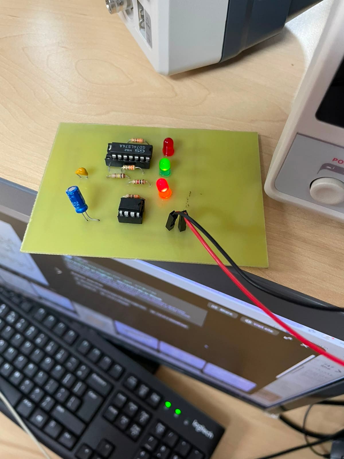
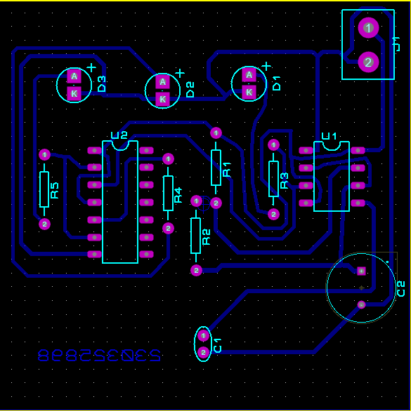
Single-layer PCB layout for the printed circuit board project
Electronics / PCB design

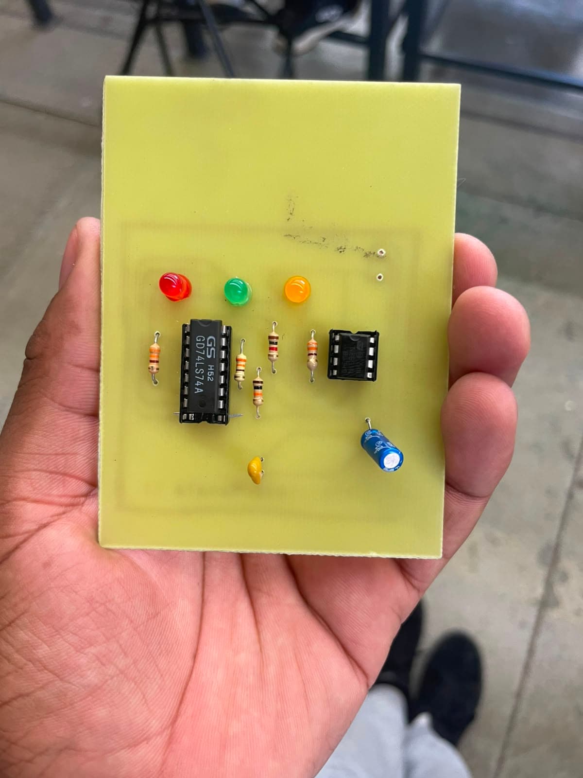
Printed circuit board project

What
Design and fabricate a toggle-switch circuit using a 555 timer IC configured in astable mode and a dual D-type flip-flop.
How
  1. Designed and simulated the circuit, PCB layout, and 3D model in Proteus 8 Professional.
  2. Transferred the mirrored layout onto a copper board, then etched, drilled, soldered, and tested the single-layer PCB.
  3. Resolved production issues through additional toner-transfer pressure, connection verification, and resoldering where needed.
Result
The design and fabrication of the toggle circuit was successfully completed using Proteus 8 Professional for simulation and PCB layout, followed by physical production through the toner-transfer method.
  • Proteus 8
  • PCB fabrication
  • 555 timer / 74LS74
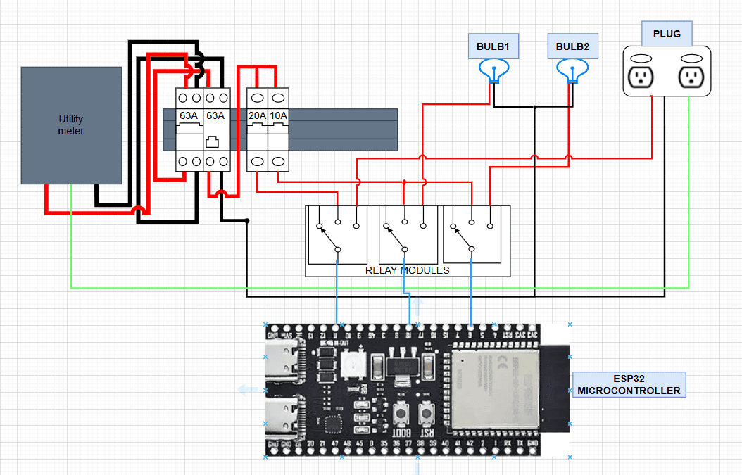
Smart home project schematic showing the ESP32, relay and light connections
Embedded systems / IoT

Smart home project

What
I built a browser-based smart home control system that uses an ESP32-S3 to switch lights over Wi-Fi and display their current status.
How
  1. Programmed the ESP32-S3 in C++ with Arduino IDE, using WiFi and WebServer libraries to host the control interface.
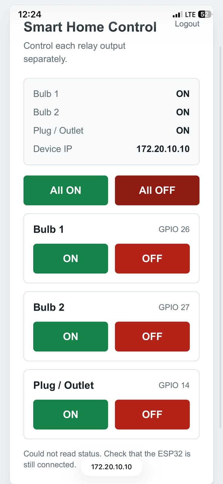
  2. Created a login-protected dashboard with separate controls for each light, status feedback, and GPIO outputs documented in the report.
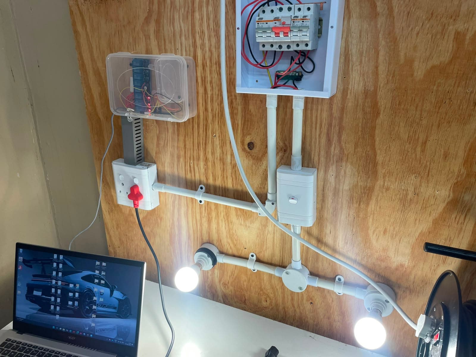
  3. Built and tested the low-voltage prototype with LEDs and relay hardware before demonstrating the final setup according to electrical safety standards.
Result
The project successfully demonstrated browser-based control of lights through an ESP32 IoT system, creating a working foundation for future smart home features such as more devices, sensors, schedules, and mobile access.
  • ESP32-S3
  • C++ / Arduino
  • Wi-Fi control
  • Web dashboard (HTML / CSS / TypeScript / Oracle SQL)
  • Electrial/Electeonics principles
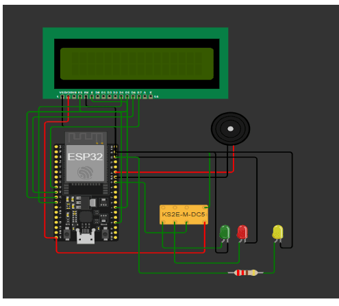
Circuit diagram for the ESP32 Bluetooth access control system
Embedded systems / smart security

Bluetooth access control system

What
Designed and implimented a secure access-control system that unlocks a relay-controlled mechanism when an authorised Bluetooth device is detected.
How
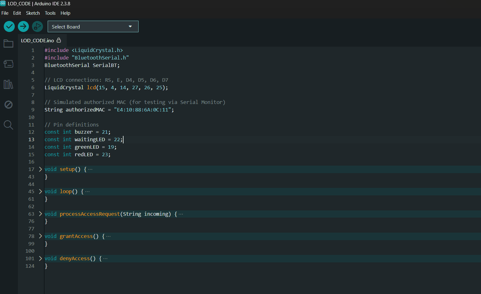
  1. Designed the ESP32 circuit with a relay, LCD display, buzzer, and green, red, and yellow status LEDs, using Arduino IDE with BluetoothSerial and LiquidCrystal libraries.
  2. Implemented MAC-address verification so the system could distinguish an authorised Bluetooth device from an unauthorised one.
  3. Tested the complete access flow, including LCD messages, LED states, buzzer patterns, and relay switching for waiting, granted, and denied scenarios.
Result
The Bluetooth-based access-control system successfully detected authorised devices and granted access, while consistently denying unauthorised devices. It responded quickly and reliably during multiple test cycles, with clear visual and audible feedback.
  • ESP32
  • Bluetooth
  • MAC verification
  • Relay control
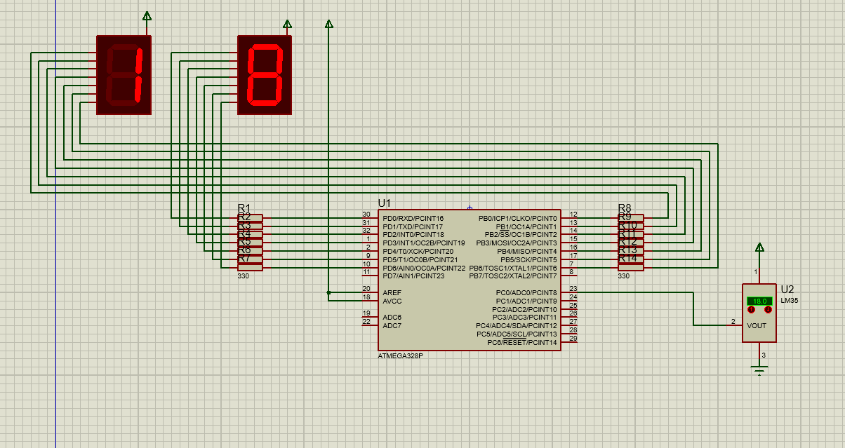
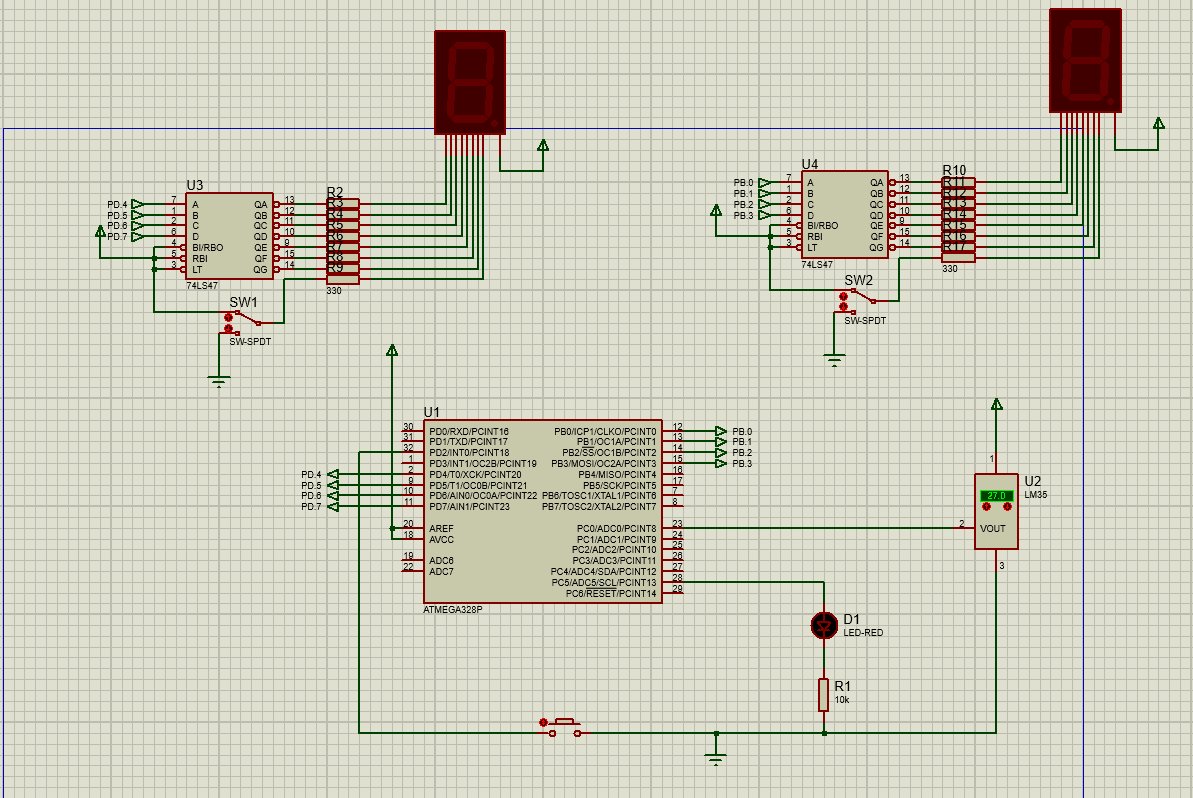
Proteus schematic for the ATmega328P temperature sensor prototype
Embedded systems / sensor design

Temperature sensor prototype

What
Designed an embedded temperature-monitoring system that measures an LM35 sensor signal and displays the temperature on two 7-segment displays.
How
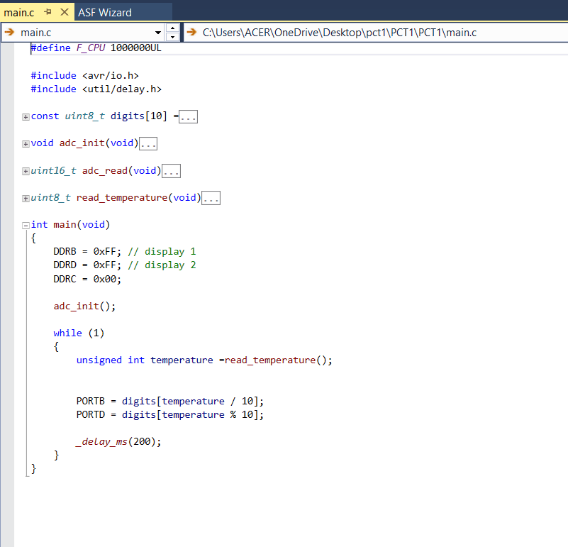
  1. Designed and simulated the circuit in Proteus using an ATmega328P, LM35 temperature sensor, two 7-segment displays, and current-limiting resistors.
  2. Programmed the microcontroller in C to read the sensor through its ADC, convert the analog voltage into a temperature value, and separate the value into tens and units digits.
  3. Troubleshot unstable readings, compilation errors, ADC configuration, and display connections through repeated verification of the circuit and program logic.
Result
The temperature-monitoring system was successfully designed and simulated. The ATmega328P correctly converted the LM35 sensor voltage into a digital temperature value and displayed it on the two 7-segment displays.
  • ATmega328P
  • LM35 sensor
  • ADC
  • Proteus simulation
Proteus schematic for the AVR dual-mode temperature and timer prototype
Embedded systems / AVR control

AVR dual-mode temperature and timer

What
Designed and simulated an interrupt-driven AVR system that counts upward to 28 and temporarily displays the temperature measured by an LM35 sensor.
How
  1. Designed and simulated the Proteus circuit using an ATmega328P, LM35 temperature sensor, 74LS47 display drivers, two 7-segment displays, and an indicator LED.
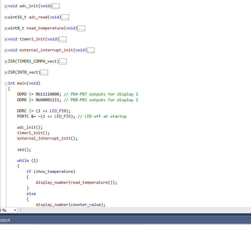
  2. Programmed the system in embedded C using the ADC to convert the sensor reading, Timer1 to manage the up-count, and interrupt routines to control the display behavior.
  3. Configured the external interrupt to interrupt the up-count and show the current temperature, demonstrating coordinated timer, ADC, and display operation.
Result
Both the up-counter and temperature display were successfully simulated. The counter operated up to 28, while the interrupt-driven temperature mode demonstrated practical understanding of AVR interrupts, timers, ADCs, and embedded C programming.
  • ATmega328P
  • AVR interrupts
  • Timer1
  • ADC
  • Embedded C